1) Release catch near centre of camera to open the
top cover.
2) Raise the cover which automatically extends the
focusing hood.
3) Press down the two side arms which will draw the
focusing hood taut and hold it rigidly in position.
4) Open front of the camera by pressing the release
lever R.
5) Pull the drop bed down until it locks itself.
6) Squeeze the spring actuated clamp of the lens
standard and pull the lens standard to the infinity
mark on the track of the drop bed.
7) Adjust fine focus with rack and pinion on right
side of the drop bed.
8) Turn diaphragm to adjust wide open and less open
aperture and check the effects on the ground glass.
9) Enjoy focusing on near by and far away objects
and practice opening and closing the drop bed.
Having said that, you know or at least would soon
find out, that there is no postcard size film on the
market anymore.
The manufacturing of the 3 1/4 x 5 1/2 format has
been discontinued in the 20th of the last century.
However there are two possibilities to try out to
take pictures with this fine classic camera.
There are still 3
1/4 x 5 1/5 roll film holders to be found on
eBay. However, as said before, unfortunately no
appropriate film.
The good news is that there are film adaptor kits
for sale on eBay to enlarge your 120 film spool to
the larger size of the old 124 Kodak Film
which was the appropriate film for the Graflex
Compact 3 1/4 x 5 1/2 camera. In other words, the
normal available 120 film spool, gets an adapter on
both sides to fits
between the spool reception mechanic of the camera.


Another option is to use the old Postcard sized film
pack holder. This holder was used with the no
more available 3x5 film pack.
These holders are often to find on eBay and mostly
very low priced.
No need to alter this film pack holder. Just a block
of wood or plastic with the size of the inside
hinged cover of the Film Pack Holder to serve as
a filler and light baffle as well.
It fills the gap between the back of the sheet of
film film and the cover of the holder and closes the
slit of the holder light tight.
You only have to cut down the 4x5 sheet film
to 3 1/4 5 inch and place it with the sensitive side
to the front with the dark slide.
Place the block on top of the sheet film back and
close the hinged cover.
Unnecessary to tell that loading the holder with
film has to be done in fully darkness.
Setting the mirror
for focusing and exposure

foto above shows the
oval top control plate with mirror control,
winding mechanism and Instant - T ime
setting plus T ime-release lever.
Pull the lever
H backwards until the mirror locks in focusing
position.
This position, with the mirror on 45 degree,
allows a view on the ground glass to focus on
the subject.
The shutter contains 5 apertures or slits
ranging from full opening to 1/8 of an inch.
When the letter O appears in window F,
the shutter is wide open.
The other apertures 1½, 3/4, 3/8, and 1/8 follow
in rotation visible in window F as the winding
key is turned to the left.
The plate mounted to the viewing hood shows the
curtain aperture.
The combination of curtain open slits and
tension of the focal plane shutter - visible in
numbers on the lower plate window G -
results in the obtainable shutter speeds.
Preparing the settings for
Instant exposure
The calculator table on
back of the focusing viewing hood will help
you to choose the exposure time setting.
Nowadays we can use an electronic exposure
meter rather than guessing. Press down lever H
into the mirror focusing position
Set bar beneath disk on I = instant
by sliding the bar D to the left to
its utmost position. I
appears left from the disk.
Now wind the curtain by turning the key to the
left, until the required number appears in the
window F.
If the curtain is set at a smaller aperture
than required, release the curtain by pressing
the lever M downward until the proper aperture
is registered at window F.
Note: as the first Compacts were not
equipped with a long lever,
operation is not easy. You may like
testing this procedure several times.
Note: A safety lock prevents the
rewinding of the curtain before the
mirror is set in focusing position. This
prevents fogging the film
making it necessary to set the mirror
before rewinding the shutter curtain.


Instant exposure
setting
Time exposure setting.
Now we move our attention to the
lower plate.
Here we're going to set the spring tension
of the focal plane shutter.
The spring tension is needed to draw the
curtain with the previous programmed slit,
down along the film surface.
To achieve this, turn the milled tension
knob B on the lower plate
anticlockwise until the appropriate number
appears in the window.
The tension numbers can be set from 1 to 6
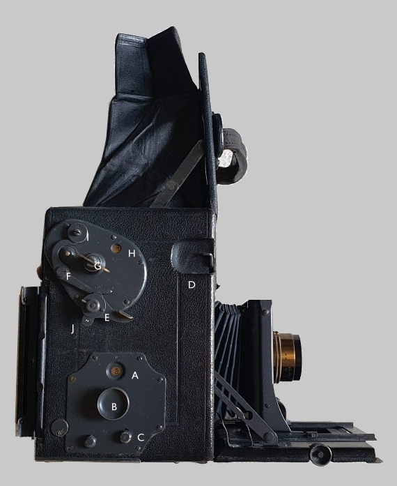
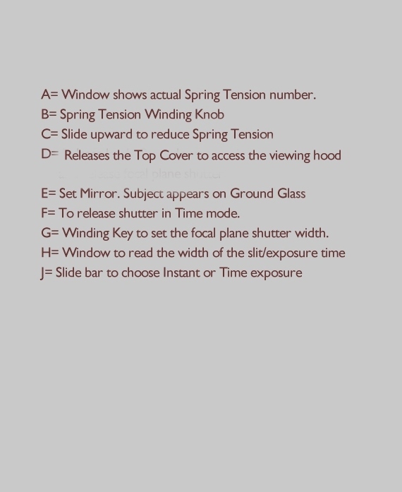
If the previous setting appears to be too
fast, the tension can be released by sliding
the escapement knob P upwards.
Each move reduces the speed one number.
Check the setting again and if they are
correct, the camera is ready for taking
photo's.
Place the film holder
slide dark slide in open position
Now the shutter has been set and the image
on the ground glass is properly focused, the
exposure is made by one gentle downward
pressure of the release lever
which is located on the forward, left hand
side of the camera body.
This pressure on the release lever
simultaneously releases the mirror and the
safety curtain.
Once the safety curtain is pulled down, the
focal plane shutter including its previous
set slit, starts its trip along the film to
expose.
Slow instantaneous exposures of about 1/5
second can be made with the curtain set at O
(full opening) and tension number on 1.
Pressure upon the shutter release causes the
mirror to rise just before the curtain with
the slit drops, closing the exposure
aperture.
What happens during the
exposure
By moving
the protruding lever H
backwards the mirror is swung in a 45
degree position. In this operative
position the image is effectively
projected on the ground glass.
When operating the exposure knob, the
mirror frame including the mirror flies
upward and closes the focusing aperture
and seals the exposure chamber from the
entrance of light from the ground glass.
The arrival of the mirror frame in
closed position pulls down the safety
curtain. Now the film exposure frame is
set free, the exposure curtain starts
its travel along the film surface.
The pre-set opening slit together with
the pre-set curtain speed tension,
exposes the film as it should be.
Time exposures
1) place the film holder against the camera back but don't open
the dark slide.
2) Press down lever H and slide the bar to
the right, exposing letter T indicating
time exposures. See picture above.
3) Wind the curtain until letter T is
registered at F.
4) After focusing the image, release the
mirror by pressing the shutter lever on
the left hand front side.
The mirror flies up against the ground
glass and leaves the mirror house wide
open to the lens. No focusing is possible
any more.
Slide the dark slide in open position
giving free access to the film.
6)To make the exposure press the lever M
downward, a second pressure on the lever M
terminates the exposure.
7) don not forget to slide the dark slide
in closed position.
Good luck!
Closing the camera
Push the bellows and lens standard
back into the camera
while pushing, hold lever H backwards.
Pull back
the mirror lever H till the utmost left
position
This is very essential.
Not following the right sequence may
lead to serious damage of the camera!
Before
storing the camera for a long period, it
must be closed, with the bellows and
lens secured inside the camera’s body.
To achieve this, the mirror setting #4
should be kept back in its utmost back
position even behind the exposure
setting and hold it.
Now squeeze the lens standard lock
and push the lens standard inwards the
camera house as far as possible.
Now the lens standard has reached its
position.
Release the lens standard lock. This
will fix this position of the lens
standard before you can close the drop
bed.
To be sure if the lens standard has its
right position please check again if the
lens standard is completely inside the
camera body.
Press side brackets to fold the drop bed
till it locks in the snap lock.
Some more
interesting technical details
The bellows storage system.

US Patent 932,457
William F. Former.
Drawing shows clearly the slant
position of the frame (7) of the
partly stretched bellows.
Fig 1
1 indicates the camera body, the
detachable back has been removed.
2 The exposure chamber
3 The bed
4 The extension bed.
5 The adjustable front.
6 The bellows
7 The tilting bellows frame pivoted
to 8
8 pivoted frame which when tilted
back to an erect position, makes
room within the body for housing the
front.
At the top of the exposing chamber
(2) there is a focusing opening 9
surrounded by a focusing hood and
fitted ground glass.

Convertible Zeiss Protar Lens F:6.3 - F:7.7
Bausch & Lomb - Zeiss Protar
Series VII focus 11 3/16
Rear lens cell Protar Series VII
focus 11 3/16

Part Two
Restoring
the Compact Graflex 3¼x5½ camera.
demands skills and experience
here are some handy tips to help
you with the first steps.
Renewing Bellows
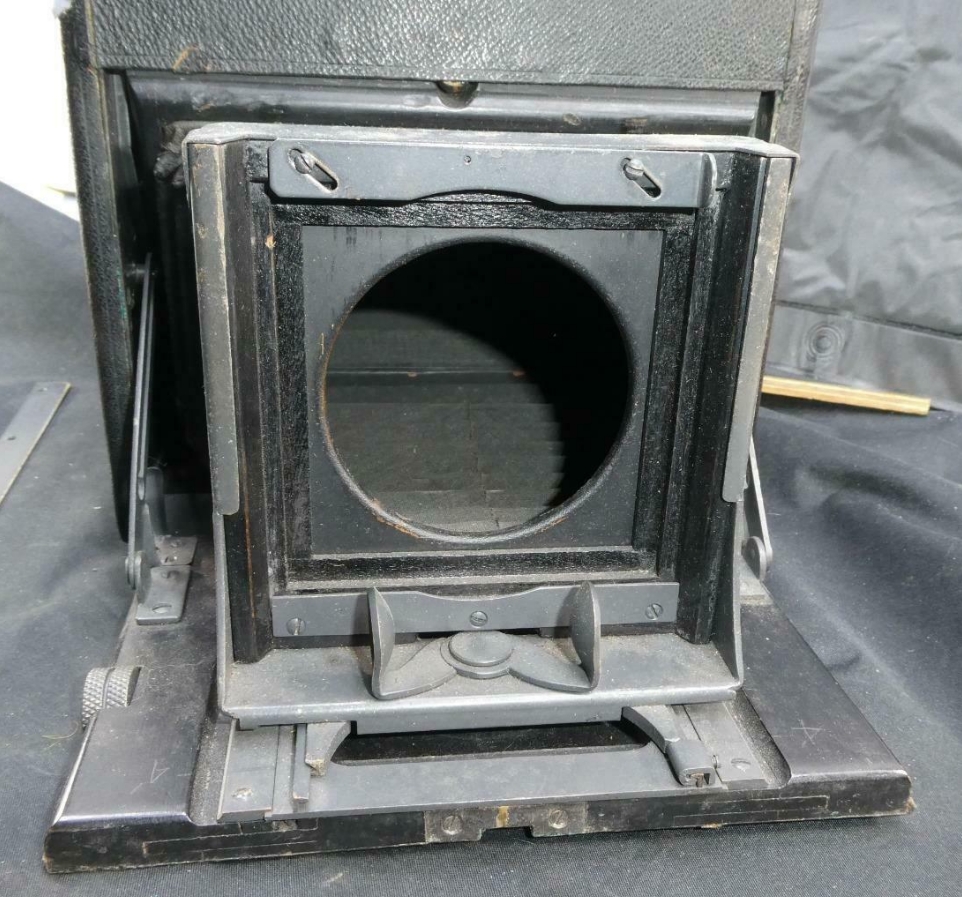

by pulling out the lens board as
far as possible the bellows may show its imperfections.
Before working on the camera, remove the focusing hood and
ground glass.
Cover the mirror to protect its silver sensitive surface coating.
Never rub such a mirror.
Cleaning only with a nylon static dust cleaner.
To start disassembling separate the bellows including
inside front plate from the back of the lens board.
-----


Photo on the
right: Backside with film
holder. Don't remove film
holder to avoid touching the
focal plane shutter or use a
cardboard protector shield.
To spare the power of the
spring make sure the mirror is
in horizontal position. Push
release knob before storing
the camera.
Start
inspection of the camera
before beginning to
disassemble.
Note the gray plate cover
protecting the mirror setting
assembly shown on the left
photo.
Right photo. Check the working
of the focal plane shutter.
Unlike most of the Graflex
focal plane shutters, this one
is equipped with a third blind
which raises
while the mirror is set
in focusing position and thus
at the same time protecting
light coming into the exposure
chamber.
Now the normal curtain setting
by key winding can be done
without the need of the dark
slide.
Check the working of this.
New Bellows for the Graflex
Compact Camera
Remove old worn Bellows
Start
the work by removing the old
worn bellows.
To remove the lens including
the lens board unscrew the
top plate of the lens
standard and slide the lens
board including the lens
upwards out of the standard.
Store the lens on a save
place.
Remove the infinity screw on
front of the track and pull
out the lens standard. The
outer board is coupled with
the board inside the
bellows.
Separate them by carefully
bending the little hooks
holding the inner lens
board. The inner lens board
can be taken off now.
If you bend the hooks too
much they might brake off,
so you better bend just
enough to be able to get the
outer board separated.


Bellows
with frame can be taken out
now.
When
working on the camera make
sure the mirror is in rest
position to protect its
surface coating.
Level H points to the front
side of the camera


The left picture shows
the Compact Camera inside
with removed bottom plate.
Picture on the right side
shows the plate with blade
spring.
The star* marked hinged
plate holds the bellows
frame
under spring tension.
This
bottom plate is equipped
with a blade spring which
keeps the bellows frame -
mounted on black hinged
plate - in its position.
While unscrewing the
screws of the bottom plate
keep the plate with one
hand tied to the camera to
avoid damage to the screw
holes in the wooden camera
body
as well as flying
screws in your work place.
After
removing the bottom plate,
The brass hinged plate
becomes visible.
6 more screws are waiting
to be unscrewed but make
notes and keep the screws
separated.
No need to dismount the
hinged drop bed.
From now on the inner
bellows assembly is free
to be removed out of the
camera housing.
The left photo shows the
partly disassembled camera
bottom.
After completely taken
down the bottom assembly,
you'll be able to pull out
the bellows frame
including the worn bellows
including the inner part
of the front lens board.
To achieve that, fold the
bellows together as much
as possible and slip this
package through the slit
in the bottom.
The advantage of this
procedure is that the
front of the camera is
open now and you'll be
able to tinker with both
hands to get the whole
package safely out of the
camera.


While
disassembling, please pay
attention to store the
screws separately and make
notes and take photos of
their original location.
Each part of this assembly
has its own screw size. It
is very important to put
them back on their
original location.


The
bellows inside the camera
house is fastened to a
wooden frame by nails and
you have to be very
careful getting the little
nails out without breaking
the frame.
Be aware that you won't
find those very tiny nails
in your local hardware
shop nor in your
surrounding world, so
you'd better try to get
them out of the frame
without spoiling them.
The separated
bellows is very useful for
taking the measurement to
create the new bellows.
Take length measurement of
the four folds and
length and width of the
frame and inner lens
board. Make a dummy out of
thin cardboard for testing
purposes.

Making
New Bellows.
The
slant shaped bellows are
not easy to design and
manufacture.
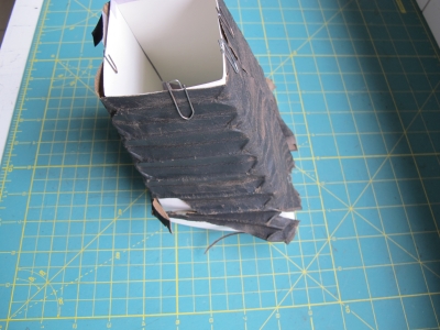
First make a paper or
cardboard dummy to check
if the old bellows fits
around it and if the
slant back fits
precisely into the
bellows frame.
Use Photo Shop® or Coral
Draw® to design the
bellows folds. Print
them on normal print
paper and glue them to
the dummy cardboard
design. (right picture
below)
9 mm for each stiffener,
2 mm for the space
between them and so
on.


cut out the space
between the stiffeners
and make sure to use
removable tape to
consolidate their
position.


If
the drawings are ready
cut two pieces of fabric
out of the BK5 Black
Nylon fabric.
One piece for the
outside and one for the
inside cover. Take at
least one inch more than
your pattern.
Only use spray glue and
and glue the stiffeners
to the BK5-Black Nylon
Blackout fabric.
You should end up with a
round closed model which
needs to be formed with
your fingers to the
bellows.

Mount
the inner lens board
into the front of the
bellows.
I used the test
cardboard dummy to hold
the new bellows strait
while working on it.
Mount the back of the
bellows to the frame
using the original tiny
nails.

I'm really happy to
present the
overhauled 1917 Compact
Graflex in perfect
working condition and
equipped with new
bellows.
Camera and
repair
Photos Jo Lommen
Graflex
Cameras
Home
Jo Lommen
camera

