The M.P.P. Micro-Press Camera.
OPENING AND CLOSING THE CAMERA
TO
OPEN THE CAMERA.
If camera is
closed you'll find the release latch under the Micro-Press tag on top of the
camera door.
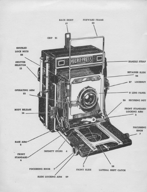
Press the base catch (1) toward the bottom of the Camera. The base or bed or
camera door, which is
under spring tension will slightly open.
Pull the base down until the base arms
(2) lock into position.
Turn the front standard locking arm (3) until it is
pointing along the baseboard and by means of the locking arm pull the front
standard (4) on to the front slide (5) until the front standard is stopped by
the (6) infinity stops.
Ensure that
both sides of the front standard are firmly engaged with the infinity stops.
Lock the front standard in this position by turning the (3) locking arm
to either the right or left.
The camera is now ready for focussing by either of the (7) focussing knobs.
TO CLOSE THE CAMERA.
Rack the
slide (5) as far back into the Camera as possible by means of the focussing
knobs (7).
Unlock the front standard (4) by turning locking arm (3) to the
front.
Push the front standard back into the Camera body as far as possible and
lock into position by turning front standard locking arm.
It is essential that the slide is
racked fully back and that the front standard is well back into the body of the
camera before attempting to close the bed.
If the slide is not racked fully back
into the body, the slide guide rails inside the camera house may break!
Depress both of the
base arms (2) and close the Camera.
INFINITY STOPS.
Before leaving the factory each Camera is calibrated for a particular lens. Focussing scale, Rangefinder and Ground Glass Screen are coordinated. To effect this calibration the infinity stops are set and used as datum points. Each lens used has its appropriate infinity stops which are hinged to allow the front standard free travel along the length of the slide. Always remember that the infinity stops are datum points and, once set, should never be moved. The selection of a pair of infinity stops for the lens in use is made easy by colour coding. The infinity stops to be used are those bearing the colour marked on the lens panel (8).
FOCUSSING.
Focussing may be accomplished in three different ways:-
(I) By
Focussing Scale.
(II) By Coupled Rangefinder.
(III) By Ground Glass Screen.
First Method
BY FOCUSING SCALE.
Select the infinity stops appropriate to the lens by the colour code. Lift the hinged stop and draw out front standard firmly against the stops and lock into position. Measure the distance from the subject to ground glass screen. (The shorter the distance the more accurate must be the measurement, particularly if using a large aperture.) Rack the slide forward by focussing knob (7) until the pointer (9) is opposite the distance on the scale (10) corresponding to the distance measured. The Camera is now in focus. Where more than one scale is fitted to the Camera the scales are colour coded exactly as lens panel and infinity stops. The scale has been calibrated to the lens supplied and is only true for that lens. 1f the scale is used with any other lens, even of the same manufacture and same nominal focal length, out of focus pictures may result.
Second Method.
BY RANGEFINDER.
First ensure that the cam* which operates the Rangefinder bears the same serial number as the lens. The cams are calculated for individual lenses and must not be used with other lenses even if they are of the same nominal focal length and made by the same manufacturer.
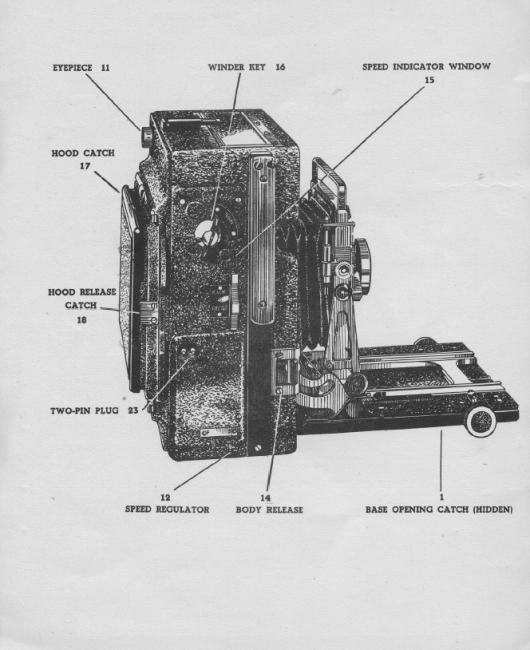
View the subject through the eye-piece (11) of the Rangefinder and rack the slide forward by focussing knob (7). Focus the small brilliant rectangle on to the subject. The subject is in focus when the two images which are present in this rectangle are superimposed.
Third Method.
BY GROUND GLASS SCREEN.
To focus by means of the Ground Glass Screen it is first necessary to ensure that both the focal plane shutter and the front shutter on the lens panel are open. To set the focal plane shutter on 'open' or 'time' position, place the speed regulator (12) in 'F' position and place the shutter selector (13) on the BACK position. The body release (14) must now be triggered until the figure '0' appears in the speed indicator window (15). Should the focal plane blind be at the end of its limit of travel a half turn of the winding key (16) will bring the figure '0' in the window.
The method of opening the front shutter depends on the type of shutter used. The method varies between Time Exposure, 'set bulb' or blade arrestor, and the manufacturers' instruction should be followed. When both focal plane shutter and front shutter are open, the spring loaded hood to the ground glass focussing screen is opened by depressing the hood catch (17). The subject can then be viewed on the ground glass screen. Rack the slide forward or backward until the subject is most sharply defined on the ground glass screen. The Camera is then in focus. 1f it is desired to use a magnifying glass for more accurate focussing, the focussing hood may be removed by releasing the catch (18).
This method of focussing, although slower than either of the former, has the advantage of allowing the operator to view the whole of the picture area and to judge the composition of the picture. It also enables him to see the depth of focus available.
VIEWFINDER.
The Camera is equipped with an open frame-finder. 'It consists of a back sight (19) and a forward frame (20) both of which are raised in operation. The forward frame is pulled out of the front standard by the grips (21) which are situated either side of the frame. The forward frame of the viewfinder has a parallax correcting scale engraved on the right-hand side which enables the height of the forward frame to be set for the selected distance.
The open frame-finder should not be relied upon to give the exact coverage of a subject, as the area seen through the viewfinder will vary considerably from person to person and is greatly affected if the operator is wearing spectacles.
TRIPOD BUSH.
Unlike the Micro Technical Camera, the Micro-Press is not fitted with a revolving back. For this reason the Camera is fitted with two tripod bushes. The bush in the base of the body is for securing the camera to a tripod when taking horizontal pictures, whilst the bush in the side of the body is for use when taking vertical pictures. The tripod bushes are the standard 3/8" Whitworth thread and adaptors can be supplied to suit the '4" Whitworth thread.
BODY RELEASE.
The body release (14) is used to trip either the focal plane shutter or the front shutter. To trip the focal plane shutter the shutter selector (13) is placed in the BACK position by pushing toward the top of the Camera. The body release will now operate the focal plane shutter. To operate the front shutter the shutter selector is pushed down to the FRONT position. The movement of the body release to the front shutter is transmitted by cable and adjustment of the operation of this cable is achieved by the knurled lock nuts (22).
FOCAL PLANE SHUTTER
The focal plane shutter is built into the rear of the camera body. It is a continuous blind with fixed width slits which ensure constant speeds. The focal plane shutter is not self-capping so that the sheath of the dark slide must be in position when the focal plane shutter is being wound. The various speeds are:--
Time.. 1/30 Sec. 1/50 Sec. 1/125 Sec.
1/250 Sec. 1/500 Sec. 1/1000 Sec.
The shutter is synchronised for "focal plane bulbs" on:
“T " 1/125, 1/250 Sec. 1/500 Sec. 1/1000 Sec.
The shutter speeds are set by winding key (16). When the shutter is fully wound and the speed regulator (12) is in position 'F' the figure of 1000 will appear in the speed indicator window (15). The shutter is now set for 1/1000 of a second. When the shutter has been triggered the figure '250' will appear in the window. The shutter is now set for 1/250 sec. When the shutter is triggered the figure '50' will appear in the window indicating that the shutter is set for 1/50 sec. 1f the shutter is again triggered the letter 'T' appears in the window to show that the shutter is set for Time Exposure. When triggered the letter '0' appears, indicating that the blind is open and it is again necessary to trigger the body release to close the shutter.
For speeds 1/30, 1/125, 1/500 the same procedure is adopted but with the speed regulator (12) placed in position 'S'.
In selecting the speeds it is, of course, only necessary to wind the blind up to the speed desired.
The speed regulator can be changed from 'F' to 'S' at any setting of the shutter.
The electrical connection to the synchronisation contact of the focal plane shutter is by the two-pin plug (23). A suitable moulded socket and length of cable to connect the flash-gun is supplied with
every Camera. It is important to note that only long duration flash bulbs designed for use with focal plane shutters should be used.
RANGEFINDER.
The Rangefinder in the Micro-Press Camera is housed in the upper compartment of the body. It consists of a stationary half-silvered mirror and a moving mirror. These components are as widely spaced as possible so as to give the long base which ensures the accuracy of the rangefinder. Movement of the Rangefinder is actuated by a *cam which is located on the back rack. The cam is fitted with dowel holes and is secured with only one screw so that it is readily detachable. The cams are engraved with the serial number of the lens with which they are associated. By these easily interchangeable cams the rangefinder may be coupled to an infinite number of lenses. To couple and use the rangefinder the following procedure is adopted:
Select the lens which it is desired to use and mount in the front standard. Pull the front standard out on to the slide up to the appropriate infinity stops and lock into position. Place the cam which is engraved with the same serial number as the lens on the dowels of the cam bracket and secure with the screw.
View the subject through the eye-piece (11). Rack the slide backward or forward as necessary until the two images of the subject which are present in the brilliant rectangle of the eye-piece are superimposed. The camera is now in focus. The rangefinder should not be used if the subject is less than two yards from the Camera.
CHANGING LENSES.
Lenses are mounted on substantial Aluminium panels which have a groove machined in their back surface. This groove engages with the register of the front standard and makes a perfect light trap.
To change a lens the two retaining slides (24) are pushed outward to the extremity of the slots and the lens is readily removed. The next lens is placed in position in the front standard and the retaining slides are pushed inwards, again to the extremity of the slots. 1f the lenses which are being changed are mounted in differing types of shutters it may be necessary to adjust the operating arm (25). 1f the arm is set too far down, the shutter will not operate on Time or Bulb.
WIDE ANGLE LENSES.
Wide Angle Lenses are mounted on the same panels as ordinary lenses and the procedure for placing them in the Camera is the same. Wide Angle Lenses with a focal length of only 3" may be used with the Micro-Press Camera. When using Wide Angle Lenses of 3" focal length the front standard is pushed back into the body against the stop and locked into position by the front standard locking arm (3). To avoid 'cut off' by the baseboard when using Wide Angle Lens the baseboard can be lowered by depressing the base arms (2) and allowing the arms to lock in their second position. The back rack on which the front standard is locked is connected to the front slide by links and the wide angle lens can be focussed by using the focussing knobs (7).
The drop baseboard is also useful when it is desired to lower the centre of the lens in respect to the plate. It is used in conjunction with the swing front. The method of operation is to pull the front standard out on to the slide, then drop the baseboard in its 'wide angle' position. The securing nuts to the swing front (26) are loosened and the swing front adjusted to bring the lens panel parallel to the plate, i.e. the limit of its travel. The securing nuts (26) are then tightened and focussing carried out. In order to make full use of the 'movement', it is, of course, necessary to employ a lens with adequate focal length. It should also be noted that all focussing should be done by ground glass screen. The rangefinder and scales are only operative when the camera is used in the normal position. After using any of the movements' care should be taken to restore the movement to normal before closing the camera.
RISING FRONT.
The Camera is provided with a rising front. Its movement is controlled by the locknuts (27). When these are loosened the front may be pulled up and locked by the locknuts (27). The rising front is extremely useful when it is desired to photograph tail buildings etc. It is often found with normal cameras that, to get the whole of a tall building on the plate, the camera must be tilted. This causes the vertical lines of the building to converge. 1f the rising front of the Micro-Press camera is used the back of the camera, or plate, can be kept parallel with the face of the building and the rising front adjusted until the whole of the building can be seen on the ground glass screen. Photographed in this way the verticals of the building will not converge.
CROSS FRONT.
The Camera is also equipped with a cross front. To use the cross front adjustment, release the front standard locking arm (3), depress the lateral shift catch (28) and move the front standard sideways. Lock in the desired position by locking arm (3). Use of this adjustment will correct excessive convergence of horizontal lines.
SLIDE LOCK.
After focussing, the slide can be locked in any position by the slide locking arm (29).
SPRING LOADED FOCUSSING SCREEN.
This permits double dark slides to be inserted with the minimum of trouble. When inserting the slide, the spring loaded focussing screen is eased from the body of the Camera by pressing the bottom of the dark slide against the two ears provided on the casting. The pressure will cause the focussing screen, which is held against the open frame of the Camera back by leaf springs, to move away from the camera body and allow the dark slide to be inserted. The dark slide is pushed home until the ridge on the dark slide engages in the groove of the Camera.
To release the dark slide, press the dark slide toward the ears of the casting until the register on the slide is disengaged, then remove the dark slide from the Camera. The focussing screen will return to its register and the Camera is again ready for focussing.
IMPORTANT.
The ground glass screen has a register of .200 inch.
Dark slides of the same register must be used.