Between-the-lens 5 blades
shutter. Flash connector Synchronized for M, F or X type lamps.
Hand or solenoid
operated, Synchronizer equipped with "OFF" position.
Cable release
socket. Shutter controls located around the shutter rim are as follows: shutter
release lever, cocking lever, press-focus lever and synchronization adjusting
lever.
Speed settings Time, Bulb 1, 1/2 - 1/5 - 1/10 - 1/25 - 1/50 - 1/100 -
1/200 and 1/400 second.
Flash equipment Graflite. Both sides of the camera are
equiped with a Flash Bracket.
The front shutter can be released by pressing the
build in shutter release.
The selector slide button 6 should be set on T which
means that the focal plane shutter stays in open position.
The shutter release
knob is now coupled with the leaf shutter if the lens rather than with the focal
plane shutter.
A very clever solution to prevent blank exposures.
It is very essential to take in consideration that working with this two-shutter
camera is a bit tricky.
I know that many users of this splendid camera removed the focal plane shutter
by cutting it off from the rollers.
The same dreadful thing obviously happened to my camera. It came with the lack
of a focal plan shutter.
The reason could be photographers often missed all their exposures due to the
fact that they
forgot to open the focal plane shutter when using the front shutter or using the
focal plane shutter with closed front shutter.
Focal Plane Shutter.
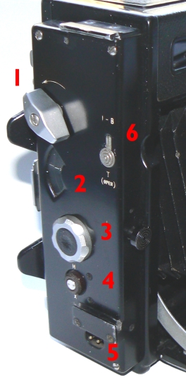 The focal plane shutter
exist out of two lightproof, black rubberised curtains wind on rollers.
The shutter is positioned on the camera back covering the exposure frame.
The
relative positions of the end of the curtains can be varied to provide
rectangular openings of different width for the control of shutter speed.
The
shutter controls located on the right side of the camera body consist of a
shutter winding knob (1)
a time setting knob (3)
with associated shutter speed dial window (2),
a selector
button (6)
and a synchro knob(4).
Synchronized speeds marked on the indicator dial are: 1/1000 - 1/500 and 1/250.
The unsynchronised speeds are T (Time) - B (bulb) 1/30 - 1/50 and 1/125.
The
selector button marked " I-B " above and " T " (open) below
is set at " I-B " for instantaneous or bulb exposures. When the focal
plane shutter is to be used for focusing on the ground glass, set dial on "B-T"
wind the shutter and then slide the selector button down to
"T" (OPEN). The shutter now runs to the open frame situation which
enables focusing on the ground glass.
To close the shutter, slide the selector
back in the I-B setting.
The
synchro terminals (5)
for the focal plane shutter
flash cable are located at the bottom of the control panel.
A synchro knob above
and to the left of the connector is turned to the " M " index marking
when flash bulbs are to be used and to the " X " marking when
electronic flash is to be used.
The shutter is self capping that means that the
shutter can be
wound without fogging the film when the dark slide of the film holder has been removed.
In other words, both blinds or curtains travel as one unit together along the
film surface not allowing light to reach the film surface.
For those who are
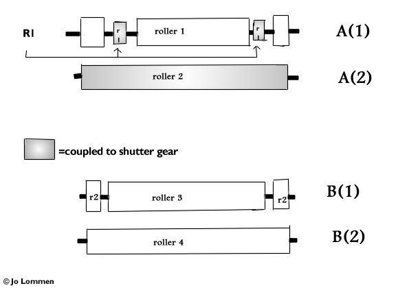
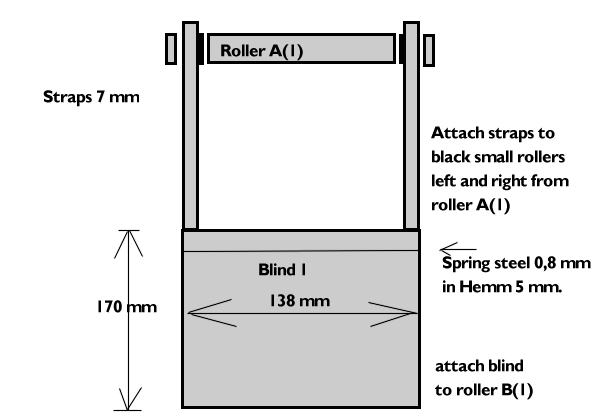
interested to know how the curtains are positioned on the rollers, herewith some
drawings to illustrate the complicated working of the focal plane shutter.
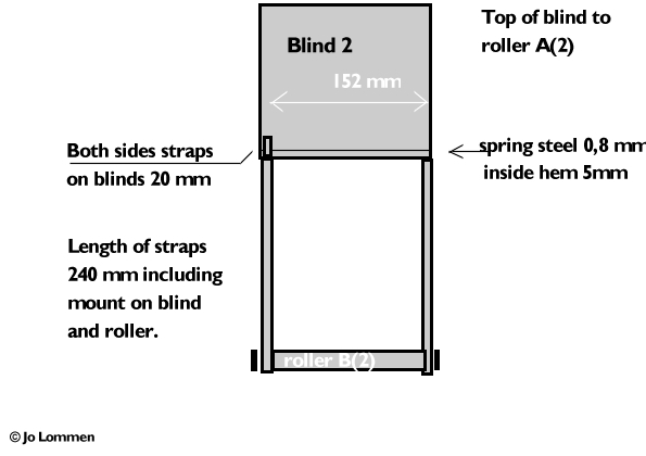
The
drawing will help you to manufacture new curtains when your camera needs new
ones.
If you are in need of the blackout fabric, please
let me know and I'll see what I can do.
Anyway make notes and take photos of
the positions of the gear before taking off the winding key.
Mark their position
with nail-polish.
If the old curtain is still present, take photos of the old
curtains' position on the rollers to help you when replacing the new curtains.
The
Beseler Focal Plane Shutter
Restoring Project.
The scarce information which could be found on
the internet about the Beseler camera and more specific of the focal plane
shutter forced me to find it out by myself.
It was clear that the focal plane
shutter should exist out of two blinds with each two straps.
First of all one
has to find out the length of each blind and its straps.
Next problem was where
exactly the straps and where the blinds should be mounted to.
The most complicated part is to find out how the mechanics, winding key gears,
sprockets and speed dial should be positioned.
The top rollers are connected to
the winding key gear and it is obvious that the whole exercise starts here.
Both
lower rollers on the underside of the shutter are equiped with tensioned
springs.
I'll spare you a long detailed and complicated explanation how this
works and confine myself to a few essential parts
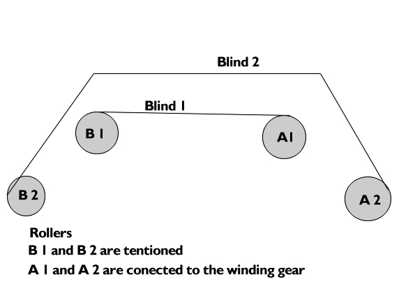
showed here below in four
drawings of the focal plane shutter blinds as well as two photographs of the
shutter assembly.
I'm far from a professional technical designer but I tried to
make it clear how the mechanics work and how the blinds should be placed.
So
please contact
me for more specific details.
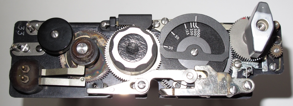
The control panel showing shutter winding key
and coupled gear, speed dial, time setting knob and synchro knob with flash
terminals.
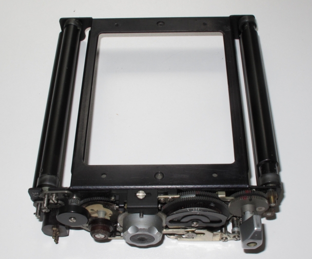
On the left the control panel cover and on the
right the stripped focal plane shutter.
These two rollers on the right are the upper
rollers and coupled to the winding key. The rollers on the left are the
lower and spring tensioned rollers.
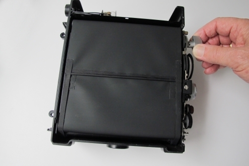
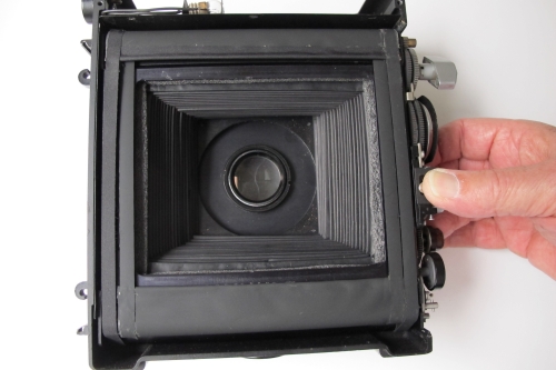
The last two photos show the "T" exposure
procedure.
Blind 1 is partly covered by blind 2 when
winding. The self capping shutter can be wound without fogging the film even
when the dark slide has been removed. Blind 2 stays in
start position while blind 1 is drawn down when selector button is on
"T" mode and the release knob has been tripped once. When tripped the
second time, the upper blind will be released and pulled down by the lower
spring roller which closes the film
frame and thus finishes the exposure. The "I-B" mode is in fact the
same procedure but the exposure runs by pressing the release button only one
time. The width of the slit provides the exposure time. Note: the spring tension
always stays equal regardless the width of the slit.
Loading Camera
Prepare camera back. Slide both slide locks to
the right. Slide the ground glass assembly into the lock bars. Insert the loaded
film holder between the back of the camera house and the ground glass assembly.
A slight backward pressure on the "ears" of the ground glass assembly
will move the frame back and facilitate insertion of the film holder. The holder
slides easily into its position. The tension of the ground glass assembly holds
the film holder tight against the camera housing thus preventing light coming
in. Draw dark slide and expose. After exposure don't forget to push back the
dark slide. You may insert the Grafmatic
holder the same way as the double film holder.
Exposure using the Focal Plane Shutter.
Set the front shutter in "T"
position. Cock the shutter and trip the release lever. The shutter opens and
stays "OPEN" allowing the use of the Focal plane shutter. Set the
focal plane shutter selector button (6) on
"I-B" position. As we already opened the front shutter, you may now
choose the exposure speed of the focal plane shutter by using the time setting
knob (3) on the side control
cover. Depress the time setting knob and turn it into the desired position
opposite the index mark on the speed indicator (2)
dial. Release the knob and let it snap into the nearest detent. Now wind the
winding knob anti-clockwise until it reaches a full stop. The shutter is now
cocked and ready for tripping.
Exposure using the Between-the-Lens Shutter.
It is the other way around. Make sure that the Focal
Plane shutter is in "Open" position. To do this, set the time
setting knob on B-T and wind the shutter anti clockwise following the arrow. Now
slide the "I-B " selector button down in "T" position.
The lower blind will be drawn down while the upper blind stays in the upper
position. The Focal Plane shutter is in "OPEN" position and thus
allowing the use of the front shutter.
More Lens Movements.
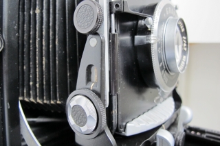
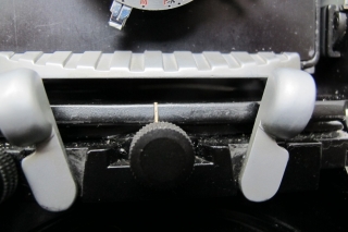
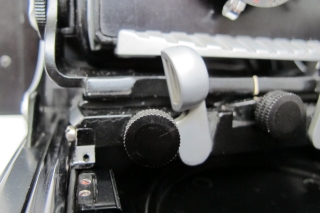
Left: Rising Front Knob - Middle: Lateral Shift
Knob and standard lock levers - Right: Lateral Swing Knob.
As mentioned before the Beseler camera is well
suited for studio work. The lens standard assembly consist of the lens board
with shutter/lens assembly, a lens standard frame assembly and support and the
sports finder assembly. On the sides of the lensboard frame assembly you'll find
the rising front lock knobs, the lens tilt and lens tilt lock
knobs used to swing the front about a horizontal axis. Furthermore
the body cable release tripper that operates the front shutter release lever.
The sportsfinder assembly slides down into grooves in the sides of the lens
board frame assembly. When the sportsfinder is pulled up into operating
position, it is used in conjunction with the peep sight on the top cover. The
lens standard support includes lens standard lock levers to hold the support in
place within the camera box or on the drop bed and extension assembly.
Furthermore a lateral swing knob used to swing the front standard about a
vertical axis and a lateral shift knob that is pulled out and rotated to
move the lens standard laterally. The lensboard frame assembly is connected to
the inside of the camera box by a light tight bellows. Note: The lens standard
assembly cannot be pushed back into the body of the camera until the extension
assembly has completely retracted (by turning the focusing knobs), in which
position the pins are depressed by the entry of two flat springs at the rear of
the rails into the rear of the bed. Thus the lens standard cannot accidentally
be pushed back off the extension track. All these features together with a nice
and ergonomic design, makes the Beseler an attractive Press Camera, for the
collector as well as for the practising amateur or professional photographer.
Beseler
Rangefinder chain repair

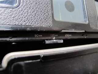
 The focal plane shutter
exist out of two lightproof, black rubberised curtains wind on rollers.


